The High Speed, Low Drag Northrop X-21
The prototype’s wing lift was artificially boosted by an extensive pattern of razor-thin slots in the upper wing surface to reduce drag.
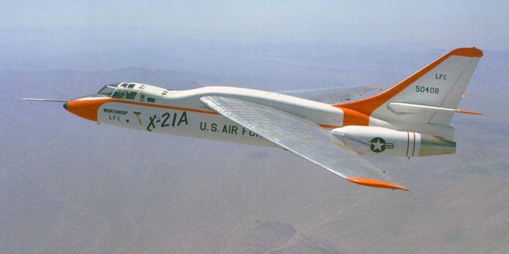
The X-21A’s wing incorporated an extensive pattern of razor-thin slots in the upper wing surface to reduce drag. [Credit: NASA photo]
If an aerospace engineer was given their choice of time periods in which to work, it’s likely the 1960s would be a top pick. With swept-wing jets like the Boeing 707 and Douglas DC-8 having made their first flights just a few years prior, the decade ahead would see the introduction of such groundbreaking aircraft as Concorde, the Boeing 747, and the XB-70 Valkyrie. Research and development budgets were robust, competition was fierce, and a young engineer looking for employment must have felt like the proverbial kid in a candy store.
While the majority of action in the U.S. centered around the production of civil airliners, military jets, and the space race, there were some less flashy but thoroughly intriguing programs taking place in some of the industry’s quieter, less-traveled corridors. One of which was a research program led by Northrop, the U.S. Air Force, and the U.S. Army. The objective? Explore how a wing’s lift could be artificially boosted to reduce drag and increase performance, particularly in large, long-range aircraft designs—some of which would be supersonic.
Drag reduction efforts were nothing new in those days. From simple efforts like flush riveting to more complex concepts like area ruling, massive progress was made in a relatively short amount of time. In the 1950s, boundary layer control (BLC) was integrated into a number of aircraft designs, a system in which compressed air was directed over sections of the wing and control surfaces to delay the separation of air over the airfoil’s surface, thus artificially increasing lift at lower airspeeds.
The team at Northrop opted to study and test something called laminar flow control, or LFC. The basic premise behind LFC is that a large number of tiny slots would be drilled into the upper surface of a wing, and a vacuum system would draw air inward through them. This would cause the thin film of air clinging to the surface of the airfoil to cling more effectively, thus reducing friction drag attributed to air turbulence over the wings by as much as 80 percent.
Because the program would be aimed at the development of civil airliners, the team chose an aircraft that would best replicate the category—the Douglas B-66 Destroyer. Specifically, it was the WB-66 weather reconnaissance version, of which 36 were built in the late 1950s. Using two examples as testbeds, the team modified them with all the necessary systems to test the LFC system.
The team began by cutting a vast series of ultra-thin slots in the upper surface of a newly-designed wing that was larger and less swept than the B-66’s original wing. These slots varied in thickness from approximately 50 percent to 200 percent of the width of the cutting edge of a razor blade. Perhaps drawing inspiration from the Bede XBD-2 that flew just a few years prior, they utilized computers to drill an intricate pattern of 800,000 pin-sized holes beneath the slots and installed hundreds of small plastic ducts inside of the wing, each one carefully tuned to a specific length to ensure proper distribution of vacuum pressure across the entirety of the wing’s upper surface.
The X-21’s GE J79 non-afterburning turbojet engines—relocated to the lower aft section of the fuselage—provided bleed air to power special compressor pumps housed in a pair of sleek nacelles mounted beneath the wing. These pumps would draw air through the slots in the wing and through the ducting to activate the LFC system. Rather than simply ejecting this compressed air overboard, it was ignited and discharged through thrust-augmenting exhaust nozzles at the aft end of each nacelle.
By the time the X-21 was completed in 1963, only the landing gear and tail surfaces remained the same as the WB-66 once was. Even the engine intakes were altered, incorporating “egg-shaped forms” within each intake that could be moved forward and aft to alter the incoming airflow. This was in anticipation of developing movable inlet cones for supersonic flight—as would be utilized on the SR-71 the following year.
The X-21 proved docile to fly, and the LFC system worked as designed. Despite having no flaps, the modified aircraft demonstrated a ground roll of 2,600 feet—significantly shorter than the required takeoff distance of the standard B-66. But while a second X-21 was built, and both contributed valuable data to the program, the team discovered a number of concerns that would preclude the adaptation of LFC into operational aircraft fleets.
As detailed in an October 1964 NASA report, the LFC system could not be relied upon during flight in clouds, haze, and high humidity. Because the tiny holes in the upper surface of the airfoils had to be kept perfectly clean and free of contamination, issues such as icing, moisture, and even insect buildup were anticipated, all of which would result in erratic performance of the LFC system. Additionally, such factors could create a dangerous asymmetric lift condition that would lead to controllability issues.
When the test program was completed, both X-21s were placed into storage at Edwards Air Force Base. Later, as their condition deteriorated, they were unceremoniously parked out in the desert, in the Edwards Photo Impact Range. There, they continue to be used to test cameras, mapping systems, and remote sensors.
This is typically where the story of such unique aircraft ends. More often than not, the scrapper is the ultimate destination, and any physical examples of the aircraft are permanently erased from history. But in the case of the X-21s, there is hope. That hope comes in the form of the Air Force Flight Test Museum, also located at Edwards Air Force Base.
There, director George Welsh is keenly aware of the X-21s and their historical value. He has already begun laying the groundwork to one day recover both examples and eventually utilize parts from both to create one representative example for display in the museum. His team has even identified a number of missing parts and has proactively scavenged them from an unrelated donor B-66, to make the future restoration process go more smoothly.
As is typically the case with even the world’s most renowned museums, funding is the primary obstacle. Having begun construction of new museum facilities, the Flight Test Museum still has to raise millions of dollars to complete that project before embarking upon the transport, storage, and restoration of the X-21s. But the museum leadership has done its duty to ensure they will be spared from the scrapper.
For now, both X-21s remain out in the desert. With any luck, the museum will soon secure enough funding to complete the new facilities so the unique jets can be restored and put on display for future generations to appreciate.

Sign-up for newsletters & special offers!
Get the latest FLYING stories & special offers delivered directly to your inbox

